

Статьи
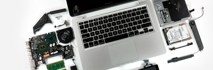
Инструкции по разбору MacBook Pro 15 (2 часть)
Heatsink
Tools
This procedure requires the following tools:
- Black stick (nylon probe 922-5065) or other non-conductive nylon or plastic fat-blade tool
- Thermal grease (922-7144)
Preliminary Steps
Before you begin, remove the following:
Battery
- Top Case
- Right Ambient Light Sensor Lens
- Fans
- Optical Drive
- Logic Board
Part Location

Procedure
1.Once the parts are removed in the preliminary steps, lift out the heatsink.

3.Make sure to install new thermal grease as outlined in the logic board chapter.
Speakers
The right and left speakers are one assembly.
Tools
This procedure requires the following tools:
- #0 Phillips screwdriver (magnetized)
- Torx T6 screwdriver (magnetized)
- Black stick (nylon probe 922-5065) or other non-conductive nylon or plastic fat-blade tool
- Kapton tape (922-1731) (0.5-inch x 12-yard roll)
Preliminary Steps
Before you begin, remove the following:
- Battery
- Top Case
- AirPort Extreme Card (for left speaker)
- Right Ambient Light Sensor Lens and MLB (for right speaker)
Part Location

Procedure
To remove the left speaker:
1.Remove Torx T6 screw from upper left of fan. Note cable routing.

2.If present, disconnect the hard drive fex connector and lift the fex cable from the
ExpressCard cage to gain access to the speaker cables and connector.
3.Note cable routing, then disconnect the speaker cable connector.

To remove the right speaker:
1.Remove the Torx T6 screw and lift out the speaker. Note: a light adhesive may be holding the
speaker in place.

2.Lift the 3 strips of black tape holding down the right speaker cable, taking care to preserve
the adhesive on the tape (rather than the bottom case) as much as possible.

Replacement note: The new speaker assembly should include replacement black tape.
Left I/O Board
Tools
This procedure requires the following tools:
- Torx T6 screwdriver (magnetized)
- 4 mm socket wrench
- Black stick (nylon probe 922-5065) or other non-conductive nylon or plastic fat-blade tool
Preliminary Steps
Before you begin, remove the following:
- Battery
- Top Case
- AirPort Extreme Card
- Left Ambient Light Sensor
- Left Speaker
Part Location

Procedure
1.Remove the four 4.2mm Torx T6 screws and single 4mm hex standof..

2.Lift the board assembly from the right side and slide away from the port openings.

3.Disconnect the cable.

Note: The ExpressCard cage is attached to the left I/O board.
4.Disconnect the fex cable.

5.Remove the four screws.

6.Lift of the card cage.

7.Replacement Note: Install the EMI gasket.

8.Replacement Note: When the board is in place and the ports are seated, hold the power
adapter port tightly against the port opening while installing screws.

9.Replacement Note: After securing the board, exercise the ExpressCard slot door to verify
clearance.
ExpressCard Cage
Tools
This procedure requires the following tools:
- #0 Phillips screwdriver (magnetized)
Preliminary Steps
Before you begin, remove the following:
- Battery
- Top Case
- AirPort Extreme Card
- Left Ambient Light Sensor
- Left Speaker
- Left I/O Board
Part Location

Procedure
See the Left I/O Board chapter for removal of the ExpressCard cage.
Bottom Case
Tools
This procedure requires no tools.
Preliminary Steps
Before you begin, remove the following:
- Battery
- Top Case
- AirPort Extreme Card
- Left Ambient Light Sensor
- Right Ambient Light Sensor Lens
- Left Speaker
- Fans
- Hard Drive
- Infrared Board
- Optical Drive
- Backup Battery
- Logic Board
- Left I/O Board
- Heatsink
- Right Speaker
- Display Assembly
Part Location

Procedure
After the parts are removed in the preliminary steps, disconnect and remove the hard drive/
infrared fex cable from the sleep LED cable. What’s left is the bottom case.
Display Assembly
Tools
This procedure requires the following tools:
- Torx T6 screwdriver (magnetized)
- Black stick (nylon probe 922-5065) or other non-conductive nylon or plastic fat-blade tool
Preliminary Steps
Before you begin, remove the following:
- Battery
- Top Case
Part Location

Procedure
1.Disconnect three antenna connectors. Lift straight up. Peel up Kapton tape to free.
2.Disconnect the iSight camera and inverter cable connectors to the right of the fan.

3.Disconnect the LVDS cable.

4.Move the display to a 90-degree angle and remove the four clutch screws.
Important: Support the display from falling over before removing the last screw.

5.Lift the display straight up and of of the computer without catching wires.

Replacement Procedure
1.Install the replacement display panel assembly.
2.Make sure to capture the LVDS cable grounding loop with the back screw.

3.Verify that the LVDS cable is secure and lays fat.
4.Reassemble and test the computer.
5.Testing the computer should include:
- Testing that the display panel functions properly.
- Use Apple System Profler to check that the AirPort Extreme card is recognized, and test
that AirPort Extreme is working.
- Check the camera function.
- Check that the trackpad and keyboard function properly.
- Operate the computer in a darkened room to check for keyboard backlight function.
Display Rear Housing
Warning: If replacing the Display Rear Housing, the correct housing must be ordered to
match the installed Display Panel, or damage can result.
Before ordering, remove the rear housing and check the manufacturer of the display panel,
such as AUO, Chi Mei or Samsung—the name will be on a label somewhere on the back
(examples shown below). Order the rear housing for the display panel manufacturer only.

Tools
This procedure requires the following tools:
- #0 Phillips screwdriver (magnetized)
- Black stick (nylon probe 922-5065) or other non-conductive nylon or plastic fat-blade tool
Preliminary Steps
Before you begin, remove the following:
Battery
- Top Case
- Display Assembly
Part Location

Procedure
1.Remove two Phillips screws.

2.Hold the display assembly up on one side and frmly push (near the middle) with your
thumbs on the edge bead to disengage the rear housing from tabs on the side of the bezel.
Note: You will not fully disengage the housing from the bezel at this point.
3.Repeat this process on the other side of the display. Note: If one side will not release, work
from the other side.

4.Use a black stick to carefully work around the clutch-side corners on both sides.
Important: The grey trim bead is part of the rear housing. Make sure to work the black stick
on the correct side of the bead


5.Lay the display on a clean, fat surface, protecting the LCD with a soft cloth. Orient the clutch
assembly downward and away from the table. Lift up on the bottom of the display housing
to completely release it from the clutch cover and bottom corners.

6.Once the clutch cover side is free, use a black stick to pry up the housing at the top of the
assembly on both sides, then move it forward to free the catches at the top, and lift of.

Replacement Procedure
Warning: If replacing the Display Rear Housing, the correct housing must be ordered to
match the installed Display Panel, or damage can result.
Before ordering, remove the rear housing and check the manufacturer of the display panel,
AUO, Chi Mei or Samsung—the name and/or logo will be on a label somewhere on the back
(examples shown at the beginning of this section). Order the rear housing for the display
panel manufacturer only.
Reassemble in the reverse sequence. Make sure housing is securely snapped together on all sides.
Display Hooks
Tools
This procedure requires the following tools:
- #0 Phillips screwdriver (magnetized)
Preliminary Steps
Before you begin, remove the following:
- Battery
- Top Case
- Display Assembly
- Display Rear Housing
Part Location

Procedure
1.Remove two Phillips screws for each hook mechanism.

Replacement note: Press on the center of the hook mechanism while screwing it into place to
prevent the mechanism from bowing out.
Sleep Magnet
Tools
This procedure requires the following tools:
- #0 Phillips screwdriver (magnetized)
Preliminary Steps
Before you begin, remove the following:
- Battery
- Top Case
- Display Assembly
- Display Rear Housing
Part Location

Procedure
The sleep magnet is primarily held in place by magnetic attraction to the metal frame around the
LCD (through the aluminum bezel). Some adhesive may be present as well.
1.To remove the magnet, use a black stick to pry it out of the small well where it resides.

Inverter Board
Note: The inverter cable is a separate assembly that includes the camera cable and can be
removed by following the procedures in the Clutch Cover chapter.
Tools
This procedure requires the following tools:
- Black stick (nylon probe 922-5065) or other non-conductive nylon or plastic fat-blade tool
Preliminary Steps
Before you begin, remove the following:
- Battery
- Top Case
- Display Assembly
- Display Rear Housing
Part Location

Procedure
1.Lift the left side of the inverter.

2.Disconnect the connector. Peel back Kapton tape as needed.

3.Lift the inverter and disconnect the connector.

General Information
Wire and Flex Cables
Because of its extremely thin enclosure design and dispersed circuit board, the MacBook Pro
utilizes a large number of fex cables and variety of wire cable harnesses. Many of these cables
carry multiple types of signals.
Here is a list of the cables and the signals that run across them. If you notice a group of functions
not working, it is likely that the cable is not properly inserted or the connector is damaged.


Microphone and Camera wires
The following photo shows the microphone wires located on the left speaker, and the camera
connector located on the logic board.

Hardware Diagnostics
AppleCare ofers two diagnostics for MacBook Pro (15-inch Core 2 Duo). Apple Hardware Test
(AHT) is shipped with every machine and targeted for end-users to troubleshoot their machine.
Apple Service Diagnostics (ASD) is ofered to Service Providers for more in-depth troubleshooting.
Both applications are available for download from Knowledge Base article 112125: Service
Diagnostics Matrix. docs.info.apple.com/article.html?artnum=112125
Apple Hardware Test (AHT) 3A115
Notes:
- Starting with MacBook Pro, the Apple Hardware Test version numbering changed. All Apple
Hardware Tests will be number sequentially starting with the prefx “3A.” This approach will
provide each AHT release a unique version number and eliminate confusion between the
same version across diferent product lines.
AHT on the DVD... follow these steps:
1.Insert the DVD named “MacBook Pro (15-inch Core 2 Duo) Mac OS X Install Disc 1” that came
with your computer.
2.Hold down “D” and restart the computer.
3.Follow the on-screen instructions.
Note: Previously, the option key was held down to boot into a boot manager. You are no longer
able to see the AHT volume using boot manager.
Apple Service Diagnostic (ASD) 3S109
Notes:
- Starting with MacBook Pro, like AHT, the Apple Service Diagnostic version numbering
changed. All ASD will be number sequentially starting with the prefx “3S.” This approach will
provide each ASD release a unique version number and eliminate confusion between the
same version across diferent product lines.
- Some older diagnostics are not on the 3S109 disk. Please keep a copy of the 3S108 disk.
Troubleshooting Aids and Tips
Power Button pads on logic board
With the top case removed, the power button is disconnected. Instead of having to reconnect the
top case to turn on the system, there are two pads on the logic board that can be shorted across
(with a tool like a fat blade screwdriver) to act as the power button.
These pads are located near the edge of the logic board, just above center of the hard drive. It is
marked PWR BTN. The pads are separated with a horizontal white line.

Resetting the Power Manager (SMC)
Power management is now handled by a chip called SMC (System Management Controller).
Previously, it was handled by the Power Management Unit (PMU). To reset the SMC:
- If the computer is on, turn it of.
- Disconnect the power adapter and remove the main battery.
- Hold the power button down for fve seconds, then release.
- Install the main battery and connect the power adapter.
- Press the power button to restart the computer.
Display off and sleep LED on
A new state was added to the sleep LED. When the system is running but the video is not turned
on (for example, briefy upon boot, or when energy saver turns of the video but does not put
the system to sleep), the sleep LED will light up uninterrupted. This feedback is to help avoid a
customer’s thinking the system is shutdown. It is possible, however, that this signal may fail if
the system has crashed. As such, you can also use the next test to see if power is present to an
apparently “of” system.
System powered test using Caps lock LED
There are situations when the system is giving indications that it is shut down (no sleep light, no
hard drive access, screen is dark, no fan, and so on); however, the logic board may still be running.
In this case, the logic board is drawing power and generating heat.
Warning: In this situation, if the computer is placed in an enclosed environment like a
carrying bag, the computer can overheat.
Check this situation by pressing the caps lock key. If the LED glows, the power manager is
running on the logic board. If instead, pressing the caps lock key and perhaps other methods of
waking up the machine have failed, including closing the lid to put it to sleep and reopening it
to wake it, hold the power button down for six seconds to force a shut down of the computer.
Restart the system to check if it boots up normally.
Note: Previously when the keyboard was connected directly to the power manager this method
worked under all conditions, however as a USB device, the OS may be hung and the keyboard
cannot respond. So if the caps lock light does not come on, the computer may be drawing power.
If in doubt, hold the power button down for six seconds to force a shut down of the computer.
Software Troubleshooting Tips and Tools
Mac OS X 10.4.8 or later only
The MacBook Pro, including the 15-inch Core 2 Duo, requires an Intel-compatible Mac OS.
Login window and account
Mac OS X requires at least one user account to be established. This is the Administrator’s account.
By default, the Accounts system preference pane has the “Log in automatically [Admin’s name]”
checked. This automatic login setting allows the system to boot into the Finder without having a
login prompt. However, if this box is not checked, you will need a password to get to the Finder.
In addition, you will need to create a user account after you reinstall system software.
Customer forgot password
If the customer forgot the password for the computer:
- Insert the MacBook Pro (15-inch Core 2 Duo) Mac OS X Install Disc 1 DVD.
- Restart the computer while holding down the C key on the keyboard.
- When the installer appears, chose Reset Password under the Installer Utilities menu.
- Follow the on-screen instructions.
Safe Mode
Safe Mode is the state Mac OS X is in after a Safe Boot. A Safe Boot is a special way to start Mac
OS X when troubleshooting. Starting up into Safe Mode does fve things to simplify the startup
and operation of your computer:
1.It forces a directory check of the startup (boot) volume. It is identical to using Disk Utility’s
Repair Disk or the fsck –fy terminal command.
2.It loads only required kernel extensions (some of the items in /System/Library/Extensions).
3.It disables all fonts other than those in /System/Library/Fonts
4.It moves to the Trash all font caches normally stored in /Library/Caches/com.apple.ATS/(uid)/,
where (uid) is a user ID number such as 501.
5.It disables all startup items and any Login Items.
To start up into Safe Mode (to Safe Boot), do this:
1.Be sure the computer is shut down.
2.Press the power button.
3.Immediately after you hear the startup tone, press and hold the Shift key.
Note: The Shift key should be held as soon as possible after the startup tone but not before.
4.Release the Shift key when you see the screen the gray Apple and progress indicator (looks
like a spinning gear). During the startup, you will see “Safe Boot” on the Mac OS X startup
screen. To leave Safe Mode, restart the computer normally, without holding any keys during
startup.
Knowledge Base Articles
These troubleshooting articles can be searched from https://www.apple.com/support.
107392 What is Safe Boot, Safe Mode?
107394 Safe Boot Takes Longer Than Normal Startup
106692 Mac OS X: Troubleshooting Installation and Software Updates
106693 Mac OS X: Troubleshooting Installation From CD-ROM
Application compatibility
With the transition to Intel Core Duo microprocessors, previous applications written for the
PowerPC microprocessor have to be re-compiled to be able to work directly with this new
microprocessor chip. As with other microprocessor transitions, Apple has formed bridges for
users and developers to aid in the changes—Universal binary and Rosetta.
Universal binary
Universal binary is a Mac OS X application created by a developer who modifes and recompiles
an application so it runs natively on either a PowerPC-based or Intel-based Mac. This application
can run on older systems and the new MacBook Pro.
A Universal binary application can work directly with the Core Duo microprocessor. As discussed
in the following section, older non-native PowerPC applications can still run on MacBook Pro, but
requires a Mac OS X technology called Rosetta to translate for the Core Duo processor.
Universal binary applications are marked with the following logo:

Rosetta
Rosetta is a Mac OS X technology which allows PowerPC applications to run on an Intel-based
Mac. Rosetta works behind the scenes to translate an existing, native, non-Universal application
(one that was designed to run natively a PowerPC-based Mac, not a Classic application—see
note) so it can run on an Intel-based Mac—all you have to do is double-click the application!
Note: The Classic (Mac OS 9) application will not run on MacBook Pro. Recommend to customers
that they upgrade to Mac OS X versions of required applications.
Knowledge Base Articles
These troubleshooting articles can be searched from https://www.apple.com/support.
303207 Intel-based Mac: How to tell if an application is Universal
303120 Intel-based Mac: Forcing a universal application to run with Rosetta
303137 Intel-based Mac: Do Classic applications work?
Hardware Symptoms
How to Use the Symptom Charts
The Symptom Charts included in this chapter will help you diagnose specifc symptoms related
to the product.
In this release, a section is dedicated to the normal startup of the Intel-based MacBook Pro (15-
inch Core 2 Duo), with a dedicated chart to identify and troubleshoot “no power, no video” and
“power, no video” symptoms.
The steps to solve a symptom are listed sequentially. You might not need to perform every
step before the symptom is resolved. Start with the frst step, and then test for the symptom. If
the symptom persists, replace any modules you removed, go to the next step, and test again.
Continue down the list until the symptom is resolved.
Startup
Startup Sequence
The Intel-based MacBook Pro starts up very much like the previous professional Macintosh
notebook computers. If power is available to the system, after pushing the power on button the
system will start to boot up.
- The screen will stay dark. The sleep LED will glow solid. This will last a few seconds.
- As the system boots, a power-on self test (POST) will be performed. See Error Codes listed
below for failure results.
- If the system is not muted, you will hear a boot beep. The backlight will turn on and the
sleep LED will turn of.
- The screen is gray in color. The Apple logo will appear and then the turning gear will appear.
- The desktop pattern will show up, as well as the menu bar start populating.
No Power, No Video
The computer will not power on (no fan movement, hard drive spin up and display is not lit).
1.Remove any connected peripherals and eject any ExpressCard.
2.Check that the battery has enough charge to start the computer by pressing the button next
to the LEDs on the battery. At least one LED must light solid (not fashing).
3.Connect a known-good Apple 85W Portable Power Adapter and power cord or plug to a
known-good power outlet; make sure the DC plug is properly inserted. The DC plug should
light up, if not, replace left I/O board. If not go to the troubleshooting, MagSafe connector.
4.Try powering up without the battery installed If it boots, try a known-good battery. If it does
not boot, replace the battery connector cable.
5.Reset the power manager or SMC. See new procedures under the “Resetting the Power
Manager” heading in the Hardware Troubleshooting Tools and Tips section.
6.Boot up the system and check the sleep indicator. If it turns on solid and turns of, the main
logic board is getting power and completing the boot cycle. If no video appears, there is an
issue getting video to the display, or system software is corrupted. Try booting from the Mac
OS X Install DVD. If the light does not turn of, the boot cycle is not being complete. This may
be caused by the hard drive not being detected by the system, system software corruption,
or possibly a hardware issue.
7.Press Caps Lock key to see if the keycap LED comes on. If it does, hold the power button
down for six seconds to shut down the computer and restart.
8.If it still doesn’t start, verify that the power button cable is connected properly to the top
case fex cable assembly and that the fex cable is connected correctly to the logic board. If
the power button is damaged or not functioning correctly, replace the top case.
9.Disconnect the keyboard completely. Inspect the connectors. Restart with the keyboard
disconnected.
10.Remove any additional RAM.
11.Try removing the AirPort Extreme card from its socket and start the computer. If it starts,
shut it down and check the fex cable connector and the connector on the logic board and
replace the damaged parts.
12.Reseat these fex cables:
• Left I/O fex cable
• Hard drive fex cable (will boot to fashing folder if not connected or corrupt)
• Optical drive fex cable
• Trackpad fex cable
• Display LVDS cable
• Thermal sensor cables
13.If the computer starts up, inspect the fex cable connector and its terminal on the logic
board for damage and replace the damaged parts.
14.Try known-good left I/O board.
15.Replace logic board.
Power-On Self Test (POST) Error Codes
The computer automatically performs a power-on self test when it is turned on after being fully
shut down (not a restart). This section describes what to do if beeps are heard during the startup.
When this occurs, the sleep LED will stay on, occasionally fashing.
MacBook Pro relies on a combination of tones and blinking sleep LEDs to display power-on self
test (POST) error codes.
If the computer detects no SDRAM (Synchronous Dynamic Random Access Memory, also referred
to as RAM), or the RAM installed does not meet the appropriate specifcations, the screen will
remain black but the power LED on the front of the computer will blink once per second to
signal the error. This error condition may be due to physically damaged RAM, installing the
incorrect type of RAM, or not having RAM installed.
Some RAM may appear to pass the power-on self test (POST) but still cannot be used by the
operating system. In this case, the computer will display a gray screen, sound three tones and
blink the power LED on the front of the computer three times, pause, and repeat the blinking
until the computer is turned of.
Related Knowledge Base articles:
303083: Intel-based Mac Power On Self Test RAM error codes
303363: Intel-based Mac: Startup sequence and error codes, symbols
Blue screen appears (a spinning disc cursor may also be visible), Prohibitory Sign
appears (a), Kernel Panic dialog box appears (b), or Gray screen during startup

1.Make sure all external devices are disconnected and any ExpressCard ejected. If the kernel
panic goes away, troubleshoot the external device by reconnecting each device until the
panic occurs.
2.If there are two RAM cards installed in the expansion slots, remove the top card and restart.
• If symptom repeats, replace bottom card with known-good RAM card.
• If symptom does not repeat, replace top RAM card with known-good RAM card and restart.
For assistance in software troubleshooting, go to Knowledge Base article 106464: Mac OS X:
Troubleshooting a Startup Issue.
Flashing question mark appears on the screen
Note: This system will only boot the Mac OS X system that shipped with this computer or later. It
does not support booting into Mac OS 9.
1.Start up from the MacBook Pro Mac OS X Install Disc 1 DVD that came with the computer
(hold down the “C” key during restart).
2.When the Installer opens, from the Installer menu under Utilities, select Disk Utility.
3.When the Disk Utility opens, on the left hand side, all disk and volumes are listed. If you don’t
see the internal hard drive, the system is not recognizing it. Skip to the next step. Otherwise,
select the internal hard drive icon and follow the instructions under the First Aid tab to verify
the hard disk, and repair if needed. Restart the computer.
4.If Disk Utility is unable to repair a persistent directory issue or corrupt fle information,
consult the following articles for possible solutions:
106214: Using Disk Utility and fsck to resolve startup issues or perform disk maintenance
25505: Directory Issue Verifcation or Repair Is Not Part of Installation
25770: Handling “overlapped extent allocation” errors reported by Disk Utility or fsck
302411: Disk Utility reports “Underlying task reported failure” when repairing a volume
5.If the hard drive is not recognized, check the hard drive fex cable for damaged connectors (a
connector peeled of the fex cable, for example), and if bad replace the hard drive fex cable.
6.Reseat the hard drive fex cable. If still not recognized, replace the hard drive.
Important: If the computer is under warranty and data recovery is required, refer to
Knowledge Base article 31077: DriveSavers: Hard Drive Data Recovery & Warranty
Implications for important information.
7.Reinstall system software using the MacBook Pro Mac OS X Install 1 disc.
Note: Don’t forget to install both the Mac OS X system and application software.
For assistance in software troubleshooting, go to Knowledge Base article
88410: SMART: A Brief Description
152349: Mac OS X 10.3: Replacing a disk before it fails
Computer begins to power up, the fans and hard drive are spinning, pressing caps
lock key lights LED, but there is no startup chime or video
1.Reset the power manager. See new procedures under the “Resetting the Power Manager
(SMC)” heading in the Hardware Troubleshooting Tools and Tips section.
2.Try connecting an external display to check for video signal that is not being displayed on
the LCD. If no external video appears, skip to step 4 below. Otherwise proceed to step 3.
3.Check all cable and fex connections to the logic board. Try restarting.
4.Replace the logic board.
System shuts down intermittently
1.Disconnect all external peripherals and eject any ExpressCard.
2.Make sure a known-good fully charged battery is fully inserted. Check that the battery latch
is fully engaged and is not broken or getting caught before fully catching. Check battery
connection to logic board.
3.Make a visual inspection of the battery connector in the battery bay. Make sure all blades are
visible and not bent. If damaged replace the battery connector.
4.Make sure the system is not overheating, the air vents are clear and the unit was not used on
a soft surface.
5.Make sure all feet are still on the bottom case. If not, order foot replacement kit.
6.Check that the fan cables are connected and the fans are operational.
7.Remove the battery and connect known-good 85W power adapter and power cord or plug
to a known-good power source; make sure the DC plug is properly seated. The DC plug
should light up. If not, consult the MagSafe power adapter troubleshooting section.
8.Verify that both thermal sensors are well seated and there is no damage to the cables.
9.Verify that the left I/O board cable is securely connected and shows no signs of wear.
10.Try known-good left I/O board.
11.Check that thermal material between the heat exchanger and logic board is in contact by
unscrewing the logic board screws and gently pulling up on the left side of the board to
verify resistance caused by adhesion from the thermal material. If not, reinstall new thermal
materials for the processor, control ASIC, and video chip (see Logic Board Takeapart chapter).
12.Replace the logic board.
System shuts down almost immediately after startup
1.Disconnect all external peripherals and eject any ExpressCard.
2.Make sure a known-good battery is fully inserted. Check battery charge and make sure that
at least two LED charge indicators light up, otherwise connect the adapter. The adapter
should light when plugged in. If not, consult the MagSafe power adapter troubleshooting
section for further troubleshooting.
3.After charging for a while, if the battery does not seem to charge, or if it is charged up but
quickly discharges, replace the battery. Verify with a known-good battery.
4.Check battery connection to logic board, and check wire attachment to connectors.
5.If just before the system shuts down, the sleep LED briefy comes on, check the two thermal
sensor connections to the main logic board. They should be fully seated with no damage to
the wiring. If the thermal sensor is damaged, replace it.
6.If a known-good battery does not charge, replace the left I/O board.
7.Replace the logic board.
Application Quits, Kernel panic or other booting problems
1.If a specifc application quits, replace the application. Verify the application is compatible
with OS X.
2.Clear parameter RAM (PRAM). Hold down Command-Option-P-R during startup until you
hear a second startup chime. For more information, consult Knowledge Base article 2238:
3.Resetting your Mac’s PRAM and NVRAM.
4.Run Disk Utility from the Software Install and Restore DVD.
Perform a clean install of system software with the software install and restore disc that
came with the computer. Note: Restore disc images are available at service.info.apple.com. Select “Disc Images.”
5.Reboot system.
6.Run Apple Service Diagnostic (ASD) in loop mode (Control-L) for an extended time to test
the memory. If the test fnds bad memory, replace the DIMMs one at a time and test until all
bad DIMMs are replaced with known-good modules.
7.Replace the logic board.
AirPort Extreme
Note: The AirPort Extreme card is now separate from the Bluetooth module. In addition, the
AirPort antenna is now in the clutch barrel behind the gray plastic window. The Bluetooth
module and antenna are now mounted underneath the top case.
AirPort Extreme not recognized
1.In Mac OS X, use Software Update in System Preferences or see the Apple Software Updates
web page to make sure the latest version of AirPort Extreme software is installed.
2.Restart the computer.
3.Open AirPort in System Preferences and make sure AirPort is on and Base Station is selected.
4.Reseat the AirPort Extreme card in its slot.
5.Remove and reinstall the AirPort Extreme software.
6.Replace with known-good AirPort Extreme card.
7.Replace left I/O board.
8.Replace the main logic board.
AirPort connection is slow
1.Move computer closer to AirPort Base Station or other AirPort device.
2.Check the number of users trying to use AirPort in the area. Too many users may be
accessing the network at the same time, causing heavy network trafc. To improve network
connection speed, add additional AirPort Base Stations.
3.Check for other changes in the environment that may cause interference with the AirPort
signal. For more information, consult Knowledge Base article 58543: AirPort: Potential
sources of interference.
4.Use Software Update in System Preferences or see the Apple Software Updates web page to
make sure the latest version of AirPort Extreme software is installed.
5.Restart the computer.
6.Check the AirPort Extreme antenna connection to the AirPort Extreme Card.
7.Reseat the AirPort Extreme card in its slot.
8.Replace with known-good AirPort Extreme w/ Bluetooth card.
9.Check AirPort Extreme antenna wires coming from clutch barrel for nicked insulator or
crimped wire. If bad, replace the AirPort Extreme antenna in the clutch barrel.
10.Replace left I/O board.
11.Replace the main logic board.
Battery
Battery will not pop up
1.Flip over the unit and slide the battery latches.
2.If the battery does not pop up, use a small plastic fat-blade tool to pry up the battery
around the battery latch.
3.Try a new battery.
4.Verify proper latch operation, by exercising the latch. If it does not move smoothly or evenly,
replace the bottom case.
5.If the latch does exercise correctly, verify that the customer is not installing the battery with
excessive force or the body of the battery has not been deformed around its perimeter.
Warning: If the battery plastic housing has been damaged, or the two halves of the
housing have separated, the battery is unsafe for use.
Note: If there is no sign of abuse (dents, scratch marks) replace the battery under warranty.
The battery won’t charge
1.Remove any externally connected peripherals.
2.Try known-good power outlet.
3.Connect known-good MagSafe 85W power adapter and power cord or plug; make sure the
DC plug is properly inserted. The DC plug should light up. If not, troubleshoot the MagSafe
connection and power adapter. If the power adapter light is green, turn over the computer
and press the battery button. The battery lights should glow green and stay on if the power
adapter is operating correctly.
4.Try a known-good battery. If it charges, replace the battery. If doesn’t charge, check the
battery connector and its connection to the logic board.
5.Replace the battery connector assembly (requires removing the logic board).
6.Reset the power manager. See new procedures under the “Resetting the Power Manager
(SMC)” heading in the Hardware Troubleshooting Tools and Tips section.
7.Make sure the left I/O cable is frmly connected. Look for damaged insulation or wires.
8.Replace left I/O power cable.
9.Replace logic board.
Battery won’t charge completely
If the battery appears to stop charging between 95 and 99 percent, this is normal operation.
Refer to Knowledge Base article 88344: PowerBook G4, iBook: battery does not show full
charge in Mac OS X.
Short battery life
Three categories to consider:
- There is a system issue (not the battery).
If you have the customer’s power adapter, plug it into a known good outlet and verify
that it can charge the system. Also make sure it is the correct 85W adapter.
Plug a known good 85W adapter into a known good outlet. Verify that the DC connector
is fully seated into the computer.
Check whether the customer’s system is setup for heavy battery power use (AirPort on,
optical media always in drive, Energy Savings set to Highest Performance, etc.)
Test the computer with all third-party devices (printers, hubs, third-party keyboard or
mouse) removed.
Reset the power manager. See new procedures under the “Resetting the Power Manager
(SMC)” heading in the Hardware Troubleshooting Tools and Tips section.
- The battery needs calibration, or it is nearing the end of its useful life.
Calibration should be done when you frst use the battery, and every few months after. It
allows the battery to properly calculate how much power is left in the battery.
The battery is a consumable part. It can be charged and discharged only so many cycles
before it becomes depleted and can no longer hold a charge.
Note: The battery calibration procedure as follows:
1.Plug in the power adapter and fully charge your battery until the light on the power
adapter plug changes to green and the onscreen meter in the menu bar indicates
that the battery is fully charged.
2.Allow the battery to rest in the fully charged state for two hours or longer. You may
use your computer during this time as long as the adapter is plugged in.
3.Disconnect the power adapter with the computer on and start running it from the
battery. You may use your computer during this time. When your battery gets low,
you will see the low battery warning dialog on the screen.
4.Continue to keep your computer turned on until it goes to sleep.
Note: Save all your work and close all applications when the battery gets low, before
the system goes to sleep.
5.Turn of the computer or allow it to sleep for fve hours or longer.
6.Connect the power adapter and leave it connected until the battery is fully
recharged again.
The battery has a defect.
Symptoms include, but are not limited to, a relatively new battery that will not charge
at all, reports an “X” in the menu bar icon, or status light on its case that will not go out.
In the frst two cases, the battery may need calibration—try this frst. In addition, after
troubleshooting at the system level, if it is demonstrated that the battery is causing
abrupt shut-downs or goes to sleep without warning, the battery can be considered
severely degraded and follow the criteria below.
Warranty Note: If the battery was purchased (either with the computer or as a
standalone part) in the last 90 days and exhibits severely degraded performance (as
defned above) provide an in-warranty replacement. If the battery was purchased
between the last 90 to 365 days, have the customer calibrate their battery. If after
recalibration, the battery still exhibits severely degraded performance, then provide
an in-warranty replacement. If the battery was purchased more than 365 days ago, the
customer will need to purchase a new battery.
Useful Knowledge Base articles:
86440: PowerBook, iBook: Battery Life, for tips on extending battery life and explanations of
some concepts of battery use.
86284: Calibrating your computer’s battery for best performance
304301: MacBook and MacBook Pro: Battery not recognized after being fully drained
Bluetooth
Bluetooth system preference pane does not show up under hardware section of
System Preferences
1.Check for software/frmware updates on the web.
2.Check the Bluetooth card fex cable underneath the top case. Make sure the cable is not
damaged and is fully seated.
3.Check the Bluetooth fex connection to the trackpad fex.
4.Check the top case fex connection to the main logic board.
5.Replace the Bluetooth card.
6.Replace the top case.
7.Replace the logic board.
Bluetooth card not recognized by other devices
1.Open Bluetooth in System Preferences and make sure that Discoverable is checked under
the Settings tab.
2.Make sure the Bluetooth antenna is properly installed.
3.Check the Bluetooth antenna is connected to Bluetooth card.
4.Replace with known-good Bluetooth card.
5.Replace the top case.
6.Replace logic board.
Display
Display latch not working
Note: When the display is being closed, two latch hooks in the top of the display housing
should be magnetically pulled down through the slots in the top case and secured by the latch
mechanism. When the latch button is pushed, the hook should release and retract into the
display housing.
If the latch hook is broken, replace the display latch hook assembly.
When displaying a single color over the screen area, the LCD panel shows one or
more pixels that are not properly lit
To determine whether or not the display has an acceptable number of pixel anomalies, follow the
steps below:
1.Set the display image to one of the following colors: all-white display, all-red display, all-green
display, or all-blue display. Knowledge Base article 112125: Service Diagnostics Matrix, has
the LCD Tester Diagnostic Utility that will generate these patterns on the screen.
2.Using a jeweler’s loupe, pocket microscope, or other magnifying device, identify and count
each pixel anomaly:
• Bright subpixel anomaly = subpixel that is always on
• Dark subpixel anomaly = subpixel that is always of
3.The number of acceptable pixel anomalies for this system is:
Acceptable Number of Subpixel Anomalies

4.If the number of subpixel anomalies exceeds the acceptable number listed in the above
chart, replace the display panel assembly.
Replace

5.If the number of subpixel anomalies is acceptable, explain to the customer that the pixel
anomalies are within specifcations, and no repair is necessary.
Important: Do not release the specifcations to customers. Instead, inform them that a certain
number of subpixel anomalies are considered acceptable, and these factors apply to all
manufacturers using LCD technology—not just Apple products.
When speaking with customers, please use the following explanation:
Active-matrix LCD technology uses rows and columns of addressable locations (pixels) that
render text and images on screen. Each pixel location has three separate subpixels (red, green,
and blue) that allow the image to be rendered in full color. Each subpixel has a corresponding
transistor responsible for turning the subpixel on or of.
There are typically millions of these subpixels on an LCD display. For example, the LCD panel used
in the Apple Cinema HD display is made up of 2.3 million pixels and 6.9 million red, green, and
blue subpixels. Occasionally, a transistor does not work perfectly, which may result in the afected
subpixel being turned on (bright) or turned of (dark). With the millions of subpixels on a display,
it is quite possible to have a low number of faulty transistors on an LCD. Therefore, a certain
number of subpixel anomalies are considered acceptable. Rejecting all but perfect LCD panels
would signifcantly increase the retail price for products using LCD displays. These factors apply
to all manufacturers using LCD technology—not just Apple products.
ExpressCard/34
ExpressCard will not insert into the ExpressCard slot
1.Make sure the ExpressCard is 34mm in width. The ExpressCard standard allows for 54mm
cards which will not ft in this slot.
2.Make sure the ExpressCard is right side up (cards are keyed and cannot be inserted upside
down).
3.Verify the ExpressCard is not warped or damaged in any way; if so replace the card.
4.Try a diferent ExpressCard.
5.Carefully raise the ExpressCard slot cover and check for a foreign object inside the slot.
6.If the slot cover is preventing the card from being inserted, re-seat the ExpressCard on the
left I/O board by making sure the cage is closer to the main logic board. The door catch on
the top of the ExpressCard mechanism.
8.Reseat the ExpressCard cage.
9.If the ExpressCard cage is damaged, replace it.
10.Replace the left I/O board.
ExpressCard does not mount to the desktop
1.Make sure the ExpressCard has its drivers installed.
2.Check if a known-good ExpressCard works in this slot. The ExpressCard may be bad.
3.Check the left I/O Board fex cable connection to the logic board.
4.Try inserting the card without the ExpressCard cage installed on the left I/O board. If the card
is recognized, reinstall the ExpressCard cage with the card in place.
5.Replace the ExpressCard cage.
6.Replace the left I/O fex cable.
7.Replace the logic board.
Hard Drive
Internal hard drive will not initialize:
1.Make sure the hard drive is a cable select drive set as a master (0).
2.Start up from the MacBook Pro Mac OS X install Disk 1 disc that came with the computer
(hold down the “C” key during restart).
3.When the Installer opens, from the Installer menu, select Open Disk Utility.
4.If the hard drive is recognized, format it under the Erase tab.
To format a blank hard drive:
- Boot from the MacBook Pro Mac OS X Install Disc 1 which came with the system (hold
down “C” key while booting).
- Select the desired language.
- Select Disk Utility, under the Utilities menu.
- Click the Erase tab.
- Select the hard drive in the Source pane.
- Verify that Mac OS Extended (Journaled) is selected.
- Click Erase.
Continue using the MacBook Pro Mac OS X Install Disc 1 to install the system software.
Restart the computer and run Software Update and install updates. Continue to run Software
Update until no more updates are listed.
Important: If the computer is under warranty and data recovery is required, refer to Knowledge
Base article 31077: DriveSavers: Hard Drive Data Recovery & Warranty Implications, for
important information.
Аренда и подмена
Предлагаем услугу аренды Macbook и iMac. Предоставляем аппарат на подмену на время ремонта.
Курьерская служба
Сохраним ваше время и силы, курьер заберёт на ремонт и доставит восстановленное устройство.
Гарантия до 12 месяцев
Уверены в качестве выполняемого ремонта и используемых комплектующих.
Компонентный и модульный ремонт
Выполняем компонентный ремонт, что дешевле. Также можем заменить целиком модуль.
Инженеры с большим опытом
У нас все прозрачно и честно
Спросите любого:
КОМАНДА MACPLUS
Советы экспертов: Как правильно выбрать сервис?
Никогда раньше не обращались за ремонтом электроники?
Не знаете с чего начать? В первую очередь - не переживать! Признаки хорошего и качественного сервиса видны сразу. Мы подготовили инструкцию для тех, кто ищет мастерскую или сервисный центр по ремонту Apple


Где отремонтировать Macbook, iMac и iPhone
Чек лист по выбору надежного
сервисного центра по ремонту техники Apple
Если компания на рынке уже много лет, и она успела зарекомендовать себя как эксперта, к ней обращаются, о ней пишут, ее рекомендуют. Мы знаем о чем говорим, так как 98% поступающих устройств в СЦ восстанавливется.
Нам доверяют и передают сложные случаи другие сервисные центры.
1. очереди не будет (или она будет минимальной) - вашим устройством займутся сразу.
2. вы отдаете в ремонт Macbook эксперту именно в области ремонтов Mac. Он знает все секреты этих устройств
Чтобы вы представляли, что именно вам нужно.
Проблему постараются решить. В большинстве случаев по описанию можно понять, что случилось и как устранить неисправность.